I want to share following safety incident / my experience feedback / other topic for sharing with colleagues:
How to adjusting the shaft alignment and the concentric?
As we know that the shaft alignment and the concentric between the parts of whatever pump and motor or other devices are very important process in assembling; and also it’s the key to ensure the quality of installation and repairing. Nevertheless, it is not everybody who familiarize with the adjusting process. Now I want to share one of the simplest and original way to adjust the shaft alignment and concentric with dial gauge.
We encountered pump serious damage of multi-stage high pressure type. And also the running hours of pump was just only 80 hours, we didn’t believe the fact was as same as your thought. When pump overhauled, inspected and renewed associated components, and found the mouth ring and impeller was already become hot melt and stuck together. We turned the pump manually and found it was moving freely without any hinder after assembled new parts. And then connected motor, manually turn test one more time, the result was same as before connecting. So processing next step of running test. First running 5 minutes and no any abnormal conditions happened, and then turning again with move freely. But then we tested again, the motor overload alarm came out, turning shaft and found no more freely movement. So it must be overhauled to inspect and confirm the reason. we found the mouth ring and impeller was lightly stuck together again and easier repair than first time.
Before second assembling the pump, we inspected every parts more carefully to confirm the correctly assembling as instruction guidance. Then assembled and turn testing, same as first turning. So connecting motor again and turning no more change, freely movement.
Before running test again, we checked the shaft alignment. Found the measure data was seriously out of limits with original fixing position of motor by fixed bolt pin. So it was unbelievable, as we know that the initially adjusting alignment with the servo engineer of shipyard and maker.
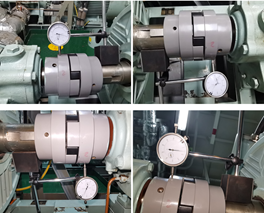

So it must be verified and adjusted the permit value of flexibility, and also to reducing some potential damage, because of, the more deviation of coupling flexibility, the more serious damage to coupling elastic, bearings, and some of other parts whatever driving side and free side. The result after adjusted as below picture showing the information.
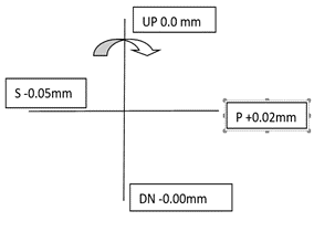
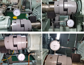
Finally running test with good performance whatever how many times running tests. And change the position of original fixing bolt pins.
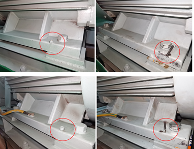
But, do you know how to adjust the shaft alignment and concentric? And I would like to introduce the detail process of adjusting shaft alignment.

Firstly, prepare dial gauge and put on coupling or shaft surface like above illustrate showing, for measuring the inclination of shaft of driving and free side. When prepared and marked first point as “0”, and then turn one circle, record the gauge reading with UP, P, Down and S (“+” indicating the shaft tail lower, and “- “indicating the shaft tail higher). If deviation exists, and then adjust it with increase or decrease shim of difference thickness. Before we carry out next step, we must ensure that the shafts of driving and free side to be keep parallel. And now, don’t care about the vertical high “L” between two shafts.
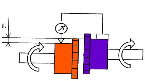
Now, we executed next step for offset the vertical height “L”, and also, put dial gauge as first step on the shaft coupling surface, but this time, the gauge touch point should be placed like above illustrate showing. Before we carry out the adjustment, we should turn the shaft one entire circle firstly to identify which side need to be adjusted. If “L” >0.00mm, it’s meaning, the touch side of dial gauge is higher than another side of shaft and touching side should be decreased the shim with suitable size. On the contrary, if “L” <0.00mm, it’s meaning lower than another side, need to be increased the shim with suitable size. If “L” =0.00mm, there is no need do anything. And to “P” and “S” of transverse of shaft, if “L” >0.00mm, it should be moved shaft to another side with suitable distance, and finally made “L” trend to 0.00mm around.
When finished first and second steps, tightened the fixing bolts. Repeat the first and second steps one more time to verify no more change of the shaft parallel and the deviation of vertical height. If any deviation beyond the permitted of instruction requirement, repeat step 1 and 2 until the reading is in the permitted range.
Hope the little tip of adjusting the shaft alignment and the concentric is helpful to your jobs, thank you!
Author: Yang Yuwei
Ship: NEW VALOR
Rank: C/E


